XTract3D Tutorial Videos
Step-by-step demonstrations of the reverse engineering process from scan to CAD.
XTract 3D Manual: Key Features Demonstration
A step-by-step demo of how to import mesh files into Xtract3D reverse engineering add-in for SOLIDWORKS.
XTract3D Workflow Video
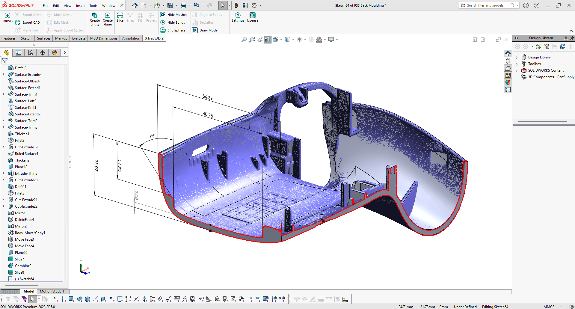
Thomas takes you on a tour of how XTract3D works by reverse engineering a nozzle. XTract3D is a reverse engineering add-in for SOLIDWORKS for converting a mesh to CAD. It has all the essential tools you need for creating CAD models from high-resolution 3D scan data exactly the way you want. It is a modern replacement for the ScanTo3D Plugin in SOLIDWORKS.
Sprocket Demo: Scan to CAD
A quick demo on how you reverse engineer a sprocket in about 10 minutes!
How to Reverse Engineer Organic Surfaces from 3D Scan Data
In this tutorial video, Thomas demonstrates how to reverse engineer a turbine blade with organic surfaces to transform 3D mesh data to a 3D solid model with SOLIDWORKS CAD modeling and XTract3D add-in.
Metal Block Demo: Scan to CAD
How to convert 3D scan data of a metal block into a native SOLIDWORKS CAD file using XTract3D reverse engineering add-in.
Using 3D Scan Data and Assembly Mode in SOLIDWORKS
XTract3D supports part and assembly mode in SOLIDWORKS to give you the freedom to integrate mesh data into the design process in different ways. Now you can use 3D scan data without reverse engineering the entire part, a first for SOLIDWORKS users. In this video, Thomas demonstrates how to partially reverse engineer scan data in part mode and to use it in assembly mode for analysis and redesign, saving valuable time.
XTract3D Advance Tutorial Video
Simon takes a look at what you need to consider when reverse engineering a part. He goes through the entire process from scan data to CAD in great detail.
