

Step 3
Create a new coordinate system
When importing scan data into SOLIDWORKS, the software places 3D meshes in an arbitrary position and rotation in space, depending on how you align the data before you import it in SOLIDWORKS.
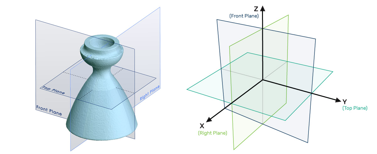
For best practices, it’s good to create a new coordinate system. SOLIDWORKS wants your part centered and aligned along the Top, Right, and Front planes so the part is centered. Orientating the part to a new coordinate system puts the 3D model in a logical space within the CAD modeling software.
For Simple Parts:
For a very simple part like the nozzle, you can use the auto-center tool (auto-center from the mesh) and align one of the flat surfaces against one of the three planes Right (x-axis), Top (y-axis), or Front (z-axis) to define center points. You can think of the Right, Top, and Front plane as (xyz axis respectively).
For Most Parts:
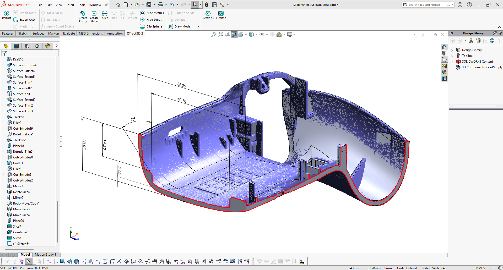
For most parts you want to create a custom coordinate system where you want more control over how the coordinate system is created. Using the SOLIDWORKS tool, go to Features → Reference Feature → Coordinate System Tool.
Start by auto-centering the part in order to have the part approximately in the right position. Next, begin a new 2D or 3D sketch that can used to define a point that represents where you want the center of the part to be. Now create line segments or points that will define the the X, Y, Z axis based on the part’s features. With one or more axis defined, you can use these features to create a custom coordinate system. After, use the Xtract3D → Use Coordinate System tool to move the mesh to the new coordinate system.
If you’re happy with the results, you can then delete the sketches and reference geometry that you used to re-orient the mesh.