Inspecting Scan Texture
A Blog Entry based on TPK Controls’ Demo Video
FlexScan3D’s “Measurement and Calculate Deviation” Tools are a cost-effective way to see if your 3D print matches the CAD model’s dimensions or you simply want to compare two different sets of data. Using the Measurement tool it is possible to inspect and extract the dimensions of the scanned data as well as planes, geometry and scan texture. The Calculate Deviation tool helps us compare 3D scan data to existing CAD or a different scan by calculating the standard deviation of each mesh point to a reference.

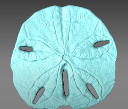
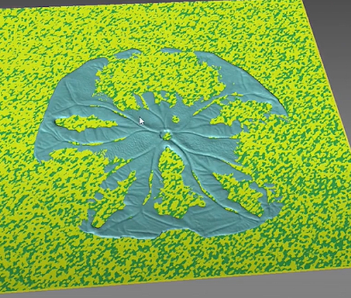
In this tutorial the described tools are used to measure the flatness and scan texture of a sand dollar. The first step is to acquire the mesh generated using FlexScan3D’s Scan Module. Since the reference to make a deviation map using the data will be a flat plane, we first take a scan of the sample model, the measured data is also known as the target. In this demonstration video, you’ll see the creation of a plane by picking out as many points as possible to get an accurate representation of the surface plane using the Measurement Tool. Later on, the plane will be converted to a mesh that will serve as the reference scan.

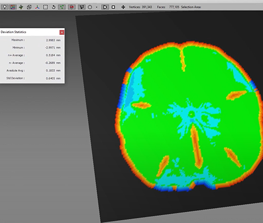
Once we have both the scanned data of the sample and the fitted plane based on its geometry, we switch to the “Calculate Deviation” module selecting the “reference” and the “target” as previously mentioned. Next step is to click on “Calculate”. Voilà! The tool outputs a statistical deviation report in just a few seconds.

The required time to compare one scan is approximately 10-20 seconds from the software. Including user operation time, assuming the user is not familiar with the software, it may take up to 30-40 seconds in total to compare one scan. For more deviation analysis inquiries, you can contact us at contact@polyga.com
Video Reference: TPK Controls – Inspecting Flat Organic & Machined Surfaces – FlexScan3D by Polyga
