


Reverse Engineering with 3DRE 3D Scanning Services
What is 3D scanning reverse engineering? Reverse engineering and 3D scanning are two related fields that have revolutionized product development and manufacturing in recent years.

Reverse engineering is the process of taking a finished product and working backwards to understand its design, materials, and manufacturing processes. This information can then be used to improve upon the original design or to create an entirely new product based on the same principles.
3D scanning, on the other hand, is a technique that uses advanced imaging technology to create an accurate, digital representation of a physical object. This digital model can then be used for a variety of purposes, including reverse engineering.
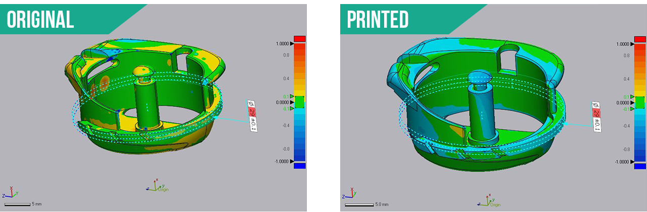
Figure 1. Matthew reverse engineers and compares a small part with the Compact S1 3D scanner.
One common use of reverse engineering and 3D scanning is in the automotive and manufacturing industry. Manufacturers use these techniques to understand the design and manufacturing processes of their client’s or competitors’ products, and then use that information to improve upon their designs.
Let’s see how our friend Matthew at 3DRE tackles his reverse engineering problems. Mathew is an Applied Science Technologist (AScTs) specializing in scanning, modeling, and inspections.
3D Scanning Reverse Engineering Case-Study
In this case study, Matthew Percivel outlines his 3D scanning reverse engineering process using the Polyga Compact S1 and Xtract3D Software. The case study involves reverse engineering of a small mechanical assembly for mass production. We first started by scanning it with the S1 scanner.
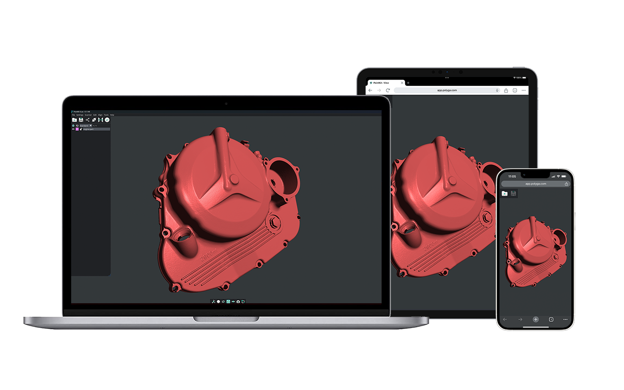
STEP 1. Use S1 to scan small parts. Once the scans are captured the data is imported into Solidworks.
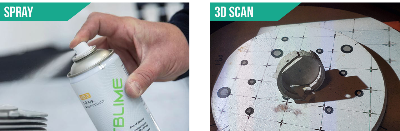
The initial part was a reflective metal so we had to use Attblime scanning spray to enhance the scan texture and capture the details. The use of Marker alignment on our manual rotary table was critical and expedited the scanning process since it was about 100 scans per part to capture all the details. The parts were 1 inch x 1 inch x 1 inch approximately.
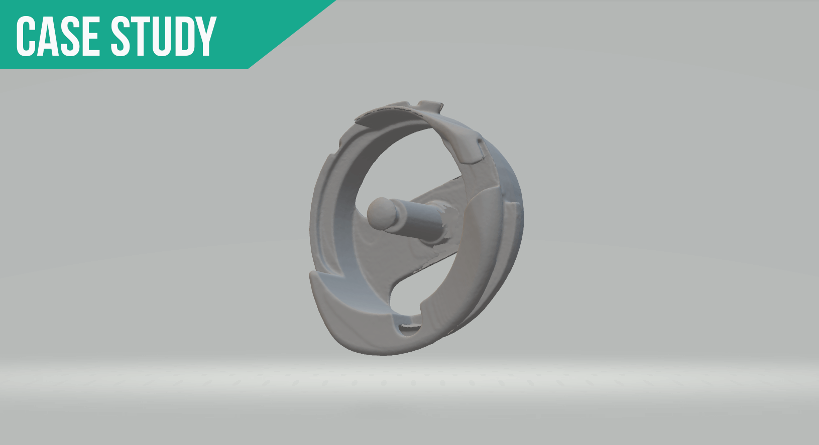
STEP 2. Using Xtract3D. Build parametric models for this reverse engineering process.
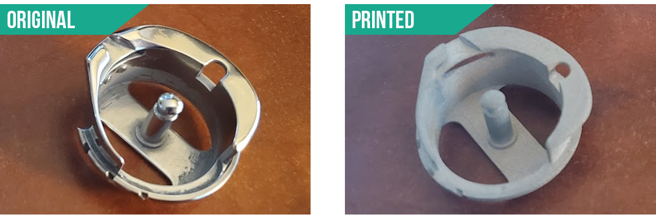
STEP 3. Get sample metal print made and compare.
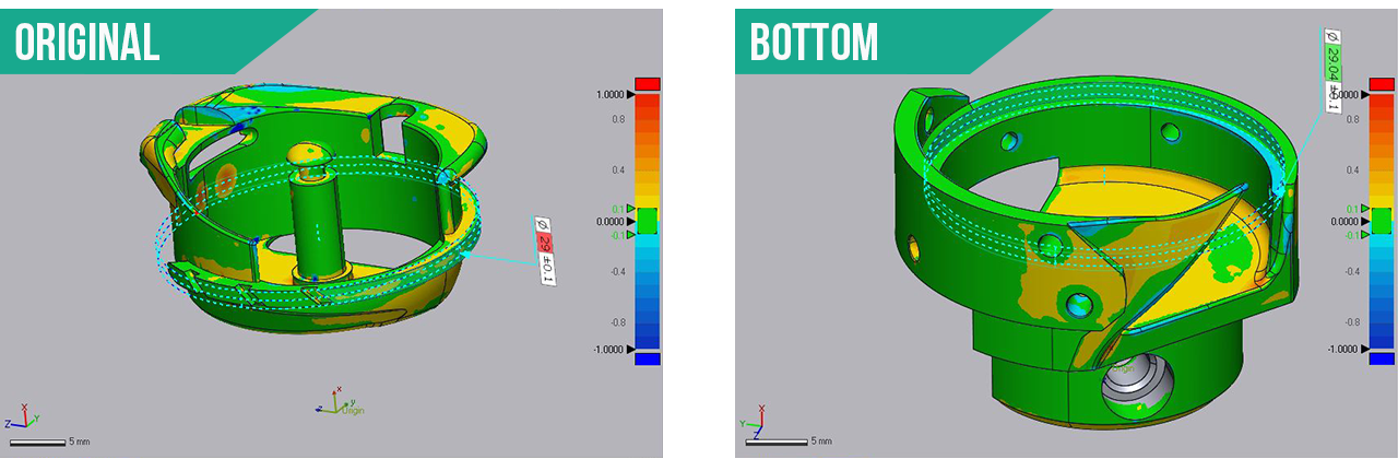
Uh oh… a discrepancy of fit; what happened? The solution is to use the S1 to inspect the 3D metal print to find out if its per the model. Scan the 3D metal prints and use the inspection tool to see what was wrong. We can use what ever solution you desire for the inspection.
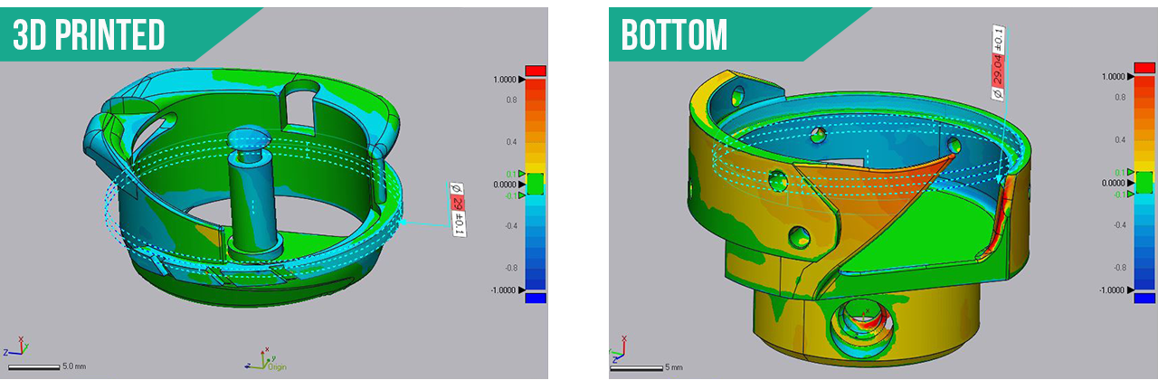
STEP 4. Scan the 3D metal prints to use the inspection tool to see what was wrong.
Eureka! The gap should be .04mm where the two parts spin within each other. Turns out they are not to the data sent! You can see that the tolerances of the circle are not correct in the Control X screen shots.
Conclusion. The S1 is a great system for small parts reverse engineering and inspection. Reverse engineering and 3D scanning can be a powerful tool for improving product design, reducing manufacturing costs and bringing new products to market faster and is critical for modern product development and manufacturing.
I hope that this will get you started on the process of 3D reverse engineering smoothly.
If you have any questions or concerns, please feel free to contact me.
All the best on your 3D scanning journey!
Best regards,

Matthew Percivel
3DRE 3D Scanning Services Ltd.
City of Langley, British Columbia, Canada
Email: info@3dre.ca
Website: 3DRE.ca